Difference between revisions of "Thermal Remediation"
(→Summary) |
(→Introduction) |
||
| Line 19: | Line 19: | ||
==Introduction== | ==Introduction== | ||
[[File:Heron-Article 1. Figure 1.PNG|400px|thumbnail|left|Figure 1. Candidate site for ISTR application with significant NAPL source material.]][[File:Heron1w1Fig2.png|right|400 px|thumbnail|right|Figure 2. The three most commonly used ''in situ'' thermal technologies. (See text for abbreviation definitions).]] | [[File:Heron-Article 1. Figure 1.PNG|400px|thumbnail|left|Figure 1. Candidate site for ISTR application with significant NAPL source material.]][[File:Heron1w1Fig2.png|right|400 px|thumbnail|right|Figure 2. The three most commonly used ''in situ'' thermal technologies. (See text for abbreviation definitions).]] | ||
| − | ISTR is typically used for source zones where conventional and less costly methods such as [[Chemical Oxidation (In Situ - ISCO) | ''in situ'' chemical oxidation]] and enhanced bioremediation are not effective<ref>Hunt, J.R., Sitar, N. and Udell, K.S., 1988. Nonaqueous phase liquid transport and cleanup: 1. Analysis of mechanisms. Water Resources Research, 24(8), 1247-1258. [http://dx.doi.org/10.1029/wr024i008p01247 doi: 10.1029/WR024i008p01247]</ref><ref>Udell, K.S., 1996. Heat and | + | ISTR is typically used for source zones where conventional and less costly methods such as [[Chemical Oxidation (In Situ - ISCO) | ''in situ'' chemical oxidation]] and enhanced bioremediation are not effective<ref name="Davis1997" /><ref>Hunt, J.R., Sitar, N. and Udell, K.S., 1988. Nonaqueous phase liquid transport and cleanup: 1. Analysis of mechanisms. Water Resources Research, 24(8), 1247-1258. [http://dx.doi.org/10.1029/wr024i008p01247 doi: 10.1029/WR024i008p01247]</ref><ref>Udell, K.S., 1996. Heat and Mass Transfer in Clean-up of Underground Toxic Wastes. In: Annual Reviews of Heat Transfer, Vol. 7, Chang-Lin Tien, Ed.; Begell House, Inc.: New York, Wallingford, UK, pgs. 333-405. [http://dx.doi.org/10.1615/annualrevheattransfer.v7.80 doi: 10.1615/AnnualRevHeatTransfer.v7.80]</ref>. For example, ISTR might be applied to a contaminated site where non-aqueous phase liquid (NAPL) has migrated to significant depth and constitutes a source zone (Figure 1). |
Most ''in situ'' thermal technologies were originally developed and applied by the oil industry to enhance oil recovery. The most widely-used technologies are listed below (Figure 2): | Most ''in situ'' thermal technologies were originally developed and applied by the oil industry to enhance oil recovery. The most widely-used technologies are listed below (Figure 2): | ||
Revision as of 13:56, 24 November 2020
In situ thermal remediation (ISTR) has gained wide acceptance over the last 20 years. It is now considered an accepted contaminant source reduction technology with a high degree of certainty for achieving remedial objectives. ISTR consists of heating subsurface groundwater and the vadose zone to facilitate volatilization or other contaminant removal mechanisms, followed by contaminant extraction and treatment. The three major ISTR technologies are Steam Enhanced Extraction (SEE), Electrical Resistance Heating (ERH) and Thermal Conduction Heating (TCH). Technology selection depends on specific site conditions, contaminant properties, and remedial objectives. At many sites, thermal technologies can be combined with less aggressive remediation methods for complete site and plume restoration (see also Thermal Remediation - Combined Remedies).
Related Article(s):
- Steam Enhanced Extraction (SEE)
- Thermal Remediation - Electrical Resistance Heating
- Thermal Conduction Heating (TCH)
- Thermal Remediation - Combined Remedies
- Thermal Remediation - Smoldering
CONTRIBUTOR(S): Dr. Gorm Heron
Key Resource(s): How Heat Can Accelerate In-situ Soil and Aquifer Remediation: Important Chemical Properties and Guidance on Choosing the Appropriate Technique[1]
Introduction
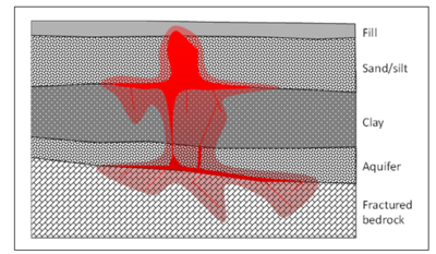
ISTR is typically used for source zones where conventional and less costly methods such as in situ chemical oxidation and enhanced bioremediation are not effective[1][2][3]. For example, ISTR might be applied to a contaminated site where non-aqueous phase liquid (NAPL) has migrated to significant depth and constitutes a source zone (Figure 1).
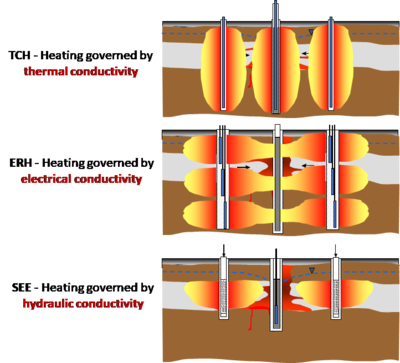
Most in situ thermal technologies were originally developed and applied by the oil industry to enhance oil recovery. The most widely-used technologies are listed below (Figure 2):
- Steam Enhanced Extraction (SEE): Steam is generated at the surface and injected into wells, sweeping to extraction wells for liquid and vapor removal[4].
- Electrical Resistance Heating (ERH): Electrodes deliver electricity and water to the subsurface, and heating occurs as the electricity meets ohmic resistance in the subsurface. Vapors are typically extracted either from the electrodes or from separate extraction wells[5].
- Thermal Conduction Heating (TCH): Simple heater borings transfer heat (no fluids) to the subsurface, and chemicals are removed by liquid and vapor extraction wells[6].
Other less commonly used ISTR technologies are hot water injection, radio-frequency heating, and micro-wave heating. For some sites with very high concentrations of hydrocarbons, smoldering may be used to degrade the contamination in place.
Applications and Strengths
There are several major applications and strengths of each of the three main ISTR technologies (Table 1). The major difference between the technologies is that TCH can be used to heat dry soils and to treat semi-volatile organic compounds (SVOCs), whereas ERH and SEE is limited by the presence of water or soil moisture, and therefore can be used to reach the boiling point water. This limits these technologies for targeting volatile organic compounds (VOCs) and to partially treat SVOCs, since temperatures are not high enough to volatilize and completely remove chemicals such as dioxins, polychlorinated biphenyls (PCBs) or PFAS.
| TCH | ERH | SEE | |
|---|---|---|---|
| Heat transfer to ground | Thermal conduction | Ohmic resistance | Steam injected directly |
| Maximum temperature achievable | >400°C | Boiling point of water | Boiling point of water |
| Injected fluids | None | Water, saline | Steam |
| Most applicable geology | All except zones with high groundwater flow |
All, well-suited for tight materials such as clays and silts |
Permeable zones |
| Contaminants treated | All organics including SVOCs | VOCs, partial treatment of SVOCs | VOCs, partial treatment of SVOCs |
| Applicability in bedrock | Yes, simple heating | Porous rock with modest resistivity | Poor – preferential flow in fractures |
| Scaling with depth | Simple heaters extended | Multiple elements stacked, if needed | Steam wells installed readily |
In general terms, ERH has been used primarily for VOC source zones, where achievement of the boiling point of water is sufficient to remediate volatile contaminants. When applicable, ERH tends to be more energy efficient than TCH and allows for faster heat-up rates TCH. SEE is used in permeable formations and can overcome cooling by groundwater flow. TCH is used in the same settings as ERH, plus at sites where treatment of less volatile contaminants of concern (COCs), such as SVOCs, is required. SEE is readily combined with other ISTR technologies for complex sites with both low permeability zones and significant groundwater flow.
Mechanisms – How are Contaminants of Concern (COCs) Removed?
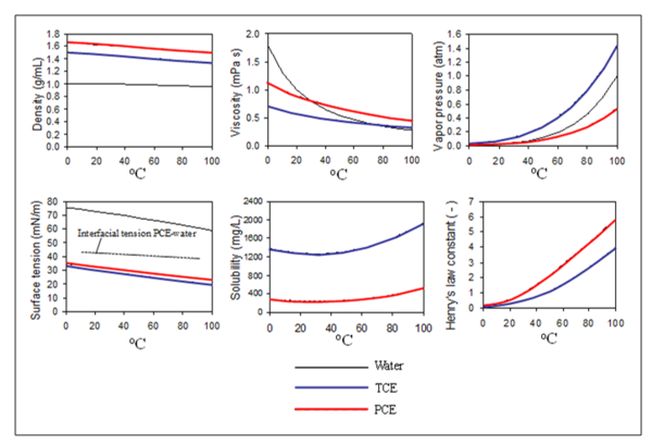
For volatile contaminants like chlorinated solvents, vaporization is the dominant mechanism for remediation. The vapor pressure and Henry's Law constant for trichloroethylene (TCE) and perchloroethylene (PCE) increase with temperature, leading to chemical vaporization once heated (Figure 3).

For oils, tars, creosote and semi-volatile chemicals, viscosity reduction to enable liquid recovery may also be an important mechanism. These fluids can then be removed by multi-phase extraction. The heating can be done with any of the three major ISTR methods. For complete removal of these less volatile chemicals, the subsurface needs to be heated to temperatures above the boiling point of water (typically between 200° and 335°C). This can only be accomplished using TCH[6].
Contaminant Extraction and Treatment
Since the goal of ISTR is to make chemicals of concern more mobile either in liquid or vapor form, subsequent extraction and capture of those COCs is essential. A site-specific analysis should determine the strategy for extraction. Because of the increased mobility of the COCs, hydraulic control must be maintained either by the use of barriers, or more often by extracting more fluids than injected for heating. Inward hydraulic gradients must be demonstrated and maintained during the heating period. Pneumatic control should be maintained by using tight vapor covers and by extracting sufficient quantities of air and steam to create a vacuum in the unsaturated part of the treatment zone.
Extracted liquids and vapors are typically cooled, separated, and treated using standard liquid and vapor treatment methods such as gravity separation, charcoal filtration, thermal oxidation, or filtering.
Monitoring During ISTR
During thermal operation, monitoring and sampling efforts are used to document progress[8] as follows:
- An energy balance is maintained and compared to modeled energy delivery and heating.
- Subsurface temperatures are documented using thermocouples or similar devices, providing near real-time documentation of the heating process.
- Mass removal rates and totals are tracked for vapor and liquid streams.
- Hydraulic and pneumatic control is documented by a combination of well-field gradient measurements and mass balance calculations.
Before completion of ISTR, confirmatory sampling of soil and groundwater is performed to document that the remedial goals have been met. Tested methods for hot sampling exist[9].
Summary
At many sites, in situ thermal technologies have provided an answer to a major challenge: how to treat heavily contaminated source zones to meet low concentration standards. The three dominant methods (SEE, ERH, TCH) have now been used at more than 300 sites. When site conditions are well understood, and the thermal system properly implemented, remediation goals have generally been met. These technologies are no longer considered innovative, and properly designed systems achieve predictable reductions in COCs.
References
- ^ 1.0 1.1 Davis, E.L., 1997. How Heat Can Accelerate In-situ Soil and Aquifer Remediation: Important Chemical Properties and Guidance on Choosing the Appropriate Technique. US EPA Issue Paper, EPA/540/S-97/502. Report pdf
- ^ Hunt, J.R., Sitar, N. and Udell, K.S., 1988. Nonaqueous phase liquid transport and cleanup: 1. Analysis of mechanisms. Water Resources Research, 24(8), 1247-1258. doi: 10.1029/WR024i008p01247
- ^ Udell, K.S., 1996. Heat and Mass Transfer in Clean-up of Underground Toxic Wastes. In: Annual Reviews of Heat Transfer, Vol. 7, Chang-Lin Tien, Ed.; Begell House, Inc.: New York, Wallingford, UK, pgs. 333-405. doi: 10.1615/AnnualRevHeatTransfer.v7.80
- ^ Udell, K.S., Sitar, N., Hunt, J.R. and Stewart Jr, L.D., 1991. Process for In Situ Decontamination of Subsurface Soil and Groundwater. The Regents of The University of California, U.S. Patent 5,018,576.
- ^ Gauglitz, P.; Roberts, J.; Bergman, T.; Schalla, R.; Caley, S.; Schlender, M.; Heath, W.; Jarosch, T.; Miller, M.; Eddy-Dilek, C.; Moss, R.; Looney, B., 1994. Six-phase soil heating for enhanced removal of contaminants: Volatile organic compounds in non-arid soils. Integrated demonstration, Savannah River Site. Report No. PNL-10184, UC-406. Pacific Northwest Laboratory, California, USA. doi: 10.2172/10193982
- ^ 6.0 6.1 Stegemeier, G.L. and Vinegar, H.J., 2001. Thermal conduction heating for in-situ thermal desorption of soils. Chapter, 4, 1-37. In Chang H. Oh (ed.), Hazardous and Radioactive Waste Treatment Technol. Handbook, CRC Press, Boca Raton, FL. ISBN 9780849395864
- ^ Heron, G., Baker, R.S., Bierschenk, J.M. and LaChance, J.C., 2006. Heat it All the Way-Mechanisms and Results Achieved using In-Situ Thermal Remediation. In Paper F-13, in: Bruce M. Sass (Conference Chair), Remediation of Chlorinated and Recalcitrant Compounds. Proceedings of the Fifth International Conference on Remediation of Chlorinated and Recalcitrant Compounds, Monterey, CA. ISBN 1-57477-157-4
- ^ Newmark, R.L. (ed.) 1994. Demonstration of Dynamic Underground Stripping at the Lawrence Livermore National Laboratory Gasoline Spill Site. Final Report UCRL-ID-116964, Vol. 1-4. Lawrence Livermore National Laboratory, Livermore, California.
- ^ Gaberell, M., Gavaskar, A., Drescher, E., Sminchak, J., Cumming, L., Yoon, W.S. and De Silva, S., 2002. Soil Core Characterization Strategy at DNAPL Sites Subjected to Strong Thermal or Chemical Remediation, In: A.R. Gavaskar and A.S.C. Chen (Eds.). Remediation of Chlorinated and Recalcitrant Compounds. Proceedings of the Third International Conference on Remediation of Chlorinated and Recalcitrant Compounds (Monterey, CA). Battelle Press, Columbus, OH. ISBN 1-57477-132-9. doi: 10.1016/j.jhazmat.2003.09.006
See Also
- Investigation of Chemical Reactivity, Mass Recovery and Biological Activity During Thermal Treatment of DNAPL Source Zones
- Large-Scale Physical Models of Thermal Remediation of DNAPL Source Zones in Aquifers
- Thermal Remediation of DNAPL Source Zones
- Contaminant Mass Transfer During Boiling in Fractured Geologic Media
- Critical Evaluation of State-of-the-Art In Situ Thermal Treatment Technologies for DNAPL Source Zone Treatment
- DNAPL Removal from Fractured Rock Using Thermal Conductive Heating
- Combining Low-Energy Electrical Resistance Heating with Biotic and Abiotic Reactions for Treatment of Chlorinated Solvent DNAPL Source Areas

